Water breakdown
Back to projects
 The final effect
Here’s a breakdown of how I created the water surface shader for my current project. It was created using C++, OpenGL and GLSL, but it should be easy to bring over the same ideas to whichever engine you’re using. Enjoy!
The final effect
Here’s a breakdown of how I created the water surface shader for my current project. It was created using C++, OpenGL and GLSL, but it should be easy to bring over the same ideas to whichever engine you’re using. Enjoy!
Surface
Mesh
 Changing the density value of the surface
The main water surface is built from a single tessellated plane that gets constructed at runtime when the water entity is created, or when any of the parameters affecting the tessellation are changed. The size and density of the plane is controlled by a 2D density value and a 2D sizing value.
This static geometry is then sent into the shader pipeline where the vertex shader, geometry shader and fragment shader all perform functions that are vital to the final look of the water.
Changing the density value of the surface
The main water surface is built from a single tessellated plane that gets constructed at runtime when the water entity is created, or when any of the parameters affecting the tessellation are changed. The size and density of the plane is controlled by a 2D density value and a 2D sizing value.
This static geometry is then sent into the shader pipeline where the vertex shader, geometry shader and fragment shader all perform functions that are vital to the final look of the water.
Vertex shader
 Sine wave displacment with wireframe on/off
The vertex shader handles displacement of the water surface. Displacement values are generated using a combination of sine waves and Gerstner waves (here's a good overview from Karman Interactive). The sine wave is fairly straightforward, but since it’s so even and smooth I keep the amplitude fairly low and just use it to create small variations.
Sine wave displacment with wireframe on/off
The vertex shader handles displacement of the water surface. Displacement values are generated using a combination of sine waves and Gerstner waves (here's a good overview from Karman Interactive). The sine wave is fairly straightforward, but since it’s so even and smooth I keep the amplitude fairly low and just use it to create small variations.
 Gerstner wave displacment, modifying the Q value
The bulk of the displacement is done by the Gerstner wave. At a very basic level Gerstner waves combine a sine wave and cosine wave to create a cresting waveform that is much closer to a genuine water surface than what you get with regular sine waves alone. The wave equation has a parameter “Q” which allows us to control how sharp we want the crests to be, and rather than simply affecting the Y-axis of the vertices it also changes how the planar XZ dimension of the vertices moves in relation to the wave. This will be important when we get to texturing and the edge foam effect.
Gerstner wave displacment, modifying the Q value
The bulk of the displacement is done by the Gerstner wave. At a very basic level Gerstner waves combine a sine wave and cosine wave to create a cresting waveform that is much closer to a genuine water surface than what you get with regular sine waves alone. The wave equation has a parameter “Q” which allows us to control how sharp we want the crests to be, and rather than simply affecting the Y-axis of the vertices it also changes how the planar XZ dimension of the vertices moves in relation to the wave. This will be important when we get to texturing and the edge foam effect.
Geometry shader
 Generated surface normals (flickering is caused by gif compression)
The geometry shader is used to rebuild the normals after they’ve been displaced in the vertex shader. This is essential since once we’ve moved the vertices around the original normals become completely invalid. The first time I implemented this design I didn’t have the ability to use geometry shaders and was forced to re-calculate the normals on the CPU which was incredibly slow, but with this relatively short shader I can take in triangles from the vertex shader and spit out the same triangles with correct normals for the fragment shader to consume.
Generated surface normals (flickering is caused by gif compression)
The geometry shader is used to rebuild the normals after they’ve been displaced in the vertex shader. This is essential since once we’ve moved the vertices around the original normals become completely invalid. The first time I implemented this design I didn’t have the ability to use geometry shaders and was forced to re-calculate the normals on the CPU which was incredibly slow, but with this relatively short shader I can take in triangles from the vertex shader and spit out the same triangles with correct normals for the fragment shader to consume.
Fragment shader
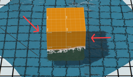
 Blending applied, refraction enabled, normal map applied.
The background surface has been given a grid texture to demonstrate the refraction effect.
The fragment shader is where all the pretty stuff happens after the vertex and geometry shaders have built the proper wave geometry for us. I won’t go over most of the lighting and materials stuff since it’s outside the scope of this write-up, and if you’re using an engine like Unreal or Unity I assume that stuff is built into the pipeline. In my case the bulk of it is automatically generated from a library of shader snippets loaded from a JSON file at runtime.
The plane geometry that we generate at the beginning is also given texture coordinates based on the size/density of the surface as well as a scaling factor that I specify. Using a diffuse texture on the surface looks a little bizarre in most scenarios, but using a normal map is really helpful to get a more textured look to the blending and refractions that I’ll talk about next.
I specify three parameters for how the water should blend overtop of the scene:
Blend: this is used to control a mix() function that combines the water surface RGB value and the current scene RGB value.
Mix: controls how much the water RGB color should be multiplied with the background color. This basically controls how much of a tint gets applied to the scene underneath the water.
Refraction: this controls the strength of the offset that is applied to the scene when viewed through the water surface. The actual GLSL refract() function isn’t used, I just offset the UV we use to sample the background based on this parameter and the current XZ value of the surface normal.
Blending applied, refraction enabled, normal map applied.
The background surface has been given a grid texture to demonstrate the refraction effect.
The fragment shader is where all the pretty stuff happens after the vertex and geometry shaders have built the proper wave geometry for us. I won’t go over most of the lighting and materials stuff since it’s outside the scope of this write-up, and if you’re using an engine like Unreal or Unity I assume that stuff is built into the pipeline. In my case the bulk of it is automatically generated from a library of shader snippets loaded from a JSON file at runtime.
The plane geometry that we generate at the beginning is also given texture coordinates based on the size/density of the surface as well as a scaling factor that I specify. Using a diffuse texture on the surface looks a little bizarre in most scenarios, but using a normal map is really helpful to get a more textured look to the blending and refractions that I’ll talk about next.
I specify three parameters for how the water should blend overtop of the scene:
Blend: this is used to control a mix() function that combines the water surface RGB value and the current scene RGB value.
Mix: controls how much the water RGB color should be multiplied with the background color. This basically controls how much of a tint gets applied to the scene underneath the water.
Refraction: this controls the strength of the offset that is applied to the scene when viewed through the water surface. The actual GLSL refract() function isn’t used, I just offset the UV we use to sample the background based on this parameter and the current XZ value of the surface normal.
Foam
A great way to add more visual interest to a water surface is to add a fringe around objects that are penetrating the surface. From here on I’ll just refer to it as “foam” since that’s basically what we’re trying to recreate. I find foam also helps ground the water in the world rather than having it look like a separate effect drawn overtop. The following is all performed in the fragment shader after regular lighting and material blending has been done.
Depth comparison
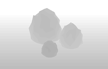
 A visualization of the depth buffer before and after the water is drawn
The technique that I use utilizes the depth buffer to compare how close the water surface is to the objects penetrating the surface and then uses that value to determine where foam should be rendered.
The main disadvantage of this technique (compared to other methods such as building foam skirts for each object by hand) is that the edges of objects, especially at right-angles, do not have foam applied to them. This is a relatively minor drawback, compared to the main advantage of this technique: it’s entirely dynamic and you can insert/extract/move/animate any of the objects in the water and the foam will react accordingly.
A visualization of the depth buffer before and after the water is drawn
The technique that I use utilizes the depth buffer to compare how close the water surface is to the objects penetrating the surface and then uses that value to determine where foam should be rendered.
The main disadvantage of this technique (compared to other methods such as building foam skirts for each object by hand) is that the edges of objects, especially at right-angles, do not have foam applied to them. This is a relatively minor drawback, compared to the main advantage of this technique: it’s entirely dynamic and you can insert/extract/move/animate any of the objects in the water and the foam will react accordingly.
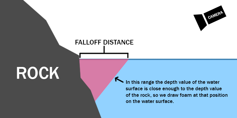 A visual breakdown of how we decide where to draw foam
 No foam is drawn because the shader does not detect an object close to the surface
Now that we know where to draw the foam, the following steps show how to achieve the look of the foam.
No foam is drawn because the shader does not detect an object close to the surface
Now that we know where to draw the foam, the following steps show how to achieve the look of the foam.
Step 1: Simple falloff
 Basic linear falloff
Once we’ve done a depth comparison to see if we should draw foam at this pixel, we need to figure out how much foam to draw.
We check our depth comparison value against our falloff distance value (which controls how far the foam effect should extend) and simply do a linear gradient so if we’re right up against an object we have a foam value of 1.0 and if we’re at the far edge of the falloff distance we should have a foam value of 0.0. I’ve also added a falloff bias parameter so that if you want a thick, hard edged foam (for a more cartoony look) you can squeeze the gradient to be full strength across the whole distance.
Basic linear falloff
Once we’ve done a depth comparison to see if we should draw foam at this pixel, we need to figure out how much foam to draw.
We check our depth comparison value against our falloff distance value (which controls how far the foam effect should extend) and simply do a linear gradient so if we’re right up against an object we have a foam value of 1.0 and if we’re at the far edge of the falloff distance we should have a foam value of 0.0. I’ve also added a falloff bias parameter so that if you want a thick, hard edged foam (for a more cartoony look) you can squeeze the gradient to be full strength across the whole distance.
 Falloff bias = 1.0
Step 2: Leading edge falloff
 Leading edge falloff applied
Since we have a foam value of 1.0 if we’re up against an object, it draws a very hard edge where the surface intersects the object. To remedy this I added a leading edge falloff parameter which creates a gradient that goes from 1.0 at the foam peak to 0.0 at the edge of the object. This is a much smaller distance since we just want to soften the edge a bit. If the pixel lies within this range then we modulate the alpha value of the water surface at the pixel.
Leading edge falloff applied
Since we have a foam value of 1.0 if we’re up against an object, it draws a very hard edge where the surface intersects the object. To remedy this I added a leading edge falloff parameter which creates a gradient that goes from 1.0 at the foam peak to 0.0 at the edge of the object. This is a much smaller distance since we just want to soften the edge a bit. If the pixel lies within this range then we modulate the alpha value of the water surface at the pixel.
Step 3: Foam texture
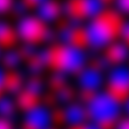
 Foam pattern
The final touch is a texture effect which gives the foam a bit more realism and movement.
I created a 256x256 texture in Photoshop by drawing tiling white circles of varying size on a black background, blurring it, and then multiplying it by [255,0,0] to get a red channel. Then I did the same with [0,0,255] to get a blue channel and combined them additively. This will be the texture that we sample in the fragment shader to achieve the foam texture.
Foam pattern
The final touch is a texture effect which gives the foam a bit more realism and movement.
I created a 256x256 texture in Photoshop by drawing tiling white circles of varying size on a black background, blurring it, and then multiplying it by [255,0,0] to get a red channel. Then I did the same with [0,0,255] to get a blue channel and combined them additively. This will be the texture that we sample in the fragment shader to achieve the foam texture.
 Tiling foam mask
I sample the texture twice (once for the red channel, once for the blue channel) using texture coordinates created from a combination of surface texture coordinates, a foam scaling parameter, a foam scrolling parameter, and some trigonometric values.
The trigonometric values help to remove any tiling artifacts that may show up. Since the sampled texture is relatively small it can be very easy to create a foam effect that is obviously tiling across a large surface, so the sine and cosine values help to resolve this.
A nice side effect of using the surface texture coordinates here is that since they are tied to the vertices, they move around when the vertices get displaced causing the foam to ebb and flow with the water displacement!
Tiling foam mask
I sample the texture twice (once for the red channel, once for the blue channel) using texture coordinates created from a combination of surface texture coordinates, a foam scaling parameter, a foam scrolling parameter, and some trigonometric values.
The trigonometric values help to remove any tiling artifacts that may show up. Since the sampled texture is relatively small it can be very easy to create a foam effect that is obviously tiling across a large surface, so the sine and cosine values help to resolve this.
A nice side effect of using the surface texture coordinates here is that since they are tied to the vertices, they move around when the vertices get displaced causing the foam to ebb and flow with the water displacement!
GLSL snippet for generating foam
vec2 scaledUV = surfaceUV * edgePatternScale;
// Sample the mask
float channelA = texture(maskSampler, scaledUV - vec2(edgePatternScroll, cos(surfaceUV.x))).r;
float channelB = texture(maskSampler, scaledUV * 0.5 + vec2(sin(surfaceUV.y), edgePatternScroll)).b;
// Modify it to our liking
float mask = (channelA + channelB) * 0.95;
mask = pow(mask, 2);
mask = clamp(mask, 0, 1);
// Is this pixel in the leading edge?
if(depthDifference < falloffDistance * leadingEdgeFalloff)
{
// Modulate the surface alpha and the mask strength
float leading = depthDifference / (falloffDistance * leadingEdgeFalloff);
fragColor.a *= leading;
mask *= leading;
}
// Calculate linear falloff value
float falloff = 1.0 - (depthDifference / falloffDistance) + edgeFalloffBias;
// Color the foam, blend based on alpha
vec3 edge = edgeFalloffColor.rgb * falloff * edgeFalloffColor.a;
// Subtract mask value from foam gradient, then add the foam value to the final pixel color
fragColor.rgb += clamp(edge - vec3(mask), 0.0, 1.0);
Once I’ve got the two texture samples I combine them. The 0.95 value and the pow() function have no basis other than they make the effect look good. Working on an effect like this is all about finding which numbers make it look the best, so feel free to experiment with other values or add any other equations you want. These two lines give us a pseudo-clamped value with a bit more softness than you would get with a standard clamp. By clamping the value of two blurred circles we get a nice blobby, fluid motion as they move past each other, similar to metaballs.
In the end what this pattern value will give us is a sort of circular cookie cutter that we can use to punch holes in our foam skirt and create the final effect. As a small addition I also use the leading edge falloff I mentioned earlier to modulate the strength of the foam cutout so that we get less of a cutout effect the closer we get to an object.
Finally we take our base gradient falloff value we calculated first, subtract our foam pattern, clamp the end result and add it to our fragment value which is then output to the screen.
The final effect
That’s all there is! I tried to include as much relevant info as I could, but since I know a lot of people will be using different pipelines I tried to keep it fairly general. If you enjoyed this or found it useful, let me know! If you’ve got any question feel free to reach out to me on twitter at @owendeery. Thanks!
Back to projects
@owendeery
owen.deery@gmail.com