This is an overview of the dynamic damage system created for the videogame Radio Viscera.
I've written this article with a focus on the concepts used rather than a specific language or environment or as a step-by-step guide. The implementation described here was built very specifically for the game I was making, so including the technical minutiae here did not seem helpful. Hopefully some of this information will help you in the development of your own project using whichever engine or environment suits you best.
I've tried to insert as many gifs, screenshots and sounds as I could to keep it from being too dry. The last few sections focus on the (less technical) secondary systems and effects that interact with the destruction and should be a bit more digestible.
This design was built in a custom C++ based game engine which uses an OpenGL renderer and the Bullet Physics SDK.
1. Overview2. Initial face generation3. Detecting raycasts and applying damage4. Drawing a damaged wall5. Collision6. Navigation7. Effects8. Doors9. Notes
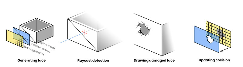
The destruction system depends on three elements that work together to present the illusion that a hole is being smashed in a wall:
Parametric geometry
Used to render the damaged walls.
Physics engine
Controls the collision shapes which make the wall solid, performs raycast queries and
helps generate triangulated collision shapes when the wall is damaged.
Render textures
Stores damage data for each wall, which is fed into the geometry shader and also used as
the source for generating collision shapes.
2. Initial face generation
Return to index
Each destructible face is built of three pieces. The first piece is the display mesh which is a parametrically generated plane with position, normal and UV coordinate data. This is used to render the face in-game.
The second piece is the collision shape. This is a static collideable rigid body which is added to the dynamics world of the physics simulation. The shape itself is an identical match for the display mesh and is positioned to sit perfectly over top. In addition to providing the collision that you would expect from a solid wall it also detects damaging raycast queries (see Detecting raycasts).
The third piece is the damage buffer. This is a 2D render texture used to store the damage state for the face. The dimensions of this texture are calculated to match the size of the face in world space multiplied by a "pixels-per-meter" factor which determines the resolution at which the damage will be stored. In my case I use 48 pixels-per-meter so a wall 4 x 2 meters in worldspace would have a 192 x 96px sized damage buffer. This texture is cleared to RGBA [0,0,0,0].
Until the wall is first damaged these three pieces do not change. The simple planar display mesh allows me to use a standard shader and render the wall like any other entity in the scene until the damage shader is required.
3. Detecting raycasts and applying damage
Return to index
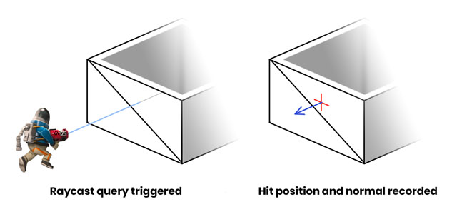
Damage is applied using raycasts. When a weapon is fired a raycast test is performed against all collision bodies in the dynamics world, with the ray originating at the weapon muzzle and extending toward the current aim direction. If the raycast intersects with the collision shape of a damageable face then a hit is registered. The world position and normal direction of the intersection are recorded and forwarded to the damageable face entity so it can record the hit to its damage buffer.
Figure 3. Surface normal of the hit is used for directional effects
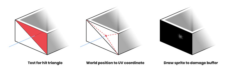
To actually apply damage a sprite needs to be drawn to the damage buffer. A black pixel on the damage buffer indicates no damage to that area and a fully white pixel indicates complete destruction of the area. Before the sprite can be drawn I need to calculate where to actually draw onto the damage buffer so it will match the hit location in world space. Barycentric coordinates will be used for this process so I first need to figure out which of the two triangles (that constitute the un-damaged plane collision shape) received the hit.
Figure 4. Steps required to draw the damage onto the buffer
Note: the barycentric method is a leftover from when the system was designed to work with arbitrary triangle meshes. If you're only dealing with flat, rectangular faces this conversion could be simplified.
Finding the correct triangle is done with a ray-triangle intersection test, using the data from the raycast hit. Since there are only two triangles this happens quickly. The destruction world position is then transformed into face-relative local space by multiplying it against the inverse transform of the wall entity. The distances between the hit position and the triangle vertices are calculated and used to generate a UV coordinate which aligns with the damage position on the wall.
Figure 5. An enlarged and brightened version of the damage sprite
The last step here is to draw the damage sprite to the damage buffer render texture like a stamp. The design of the sprite itself is the result of lots of trial and error to see what kind of shape worked well and had the intended effect (both visually and physically). The rotation of the sprite is randomized and the scale and brightness of the sprite are based on the magnitude of the damage. This allows more powerful hits to make larger holes. The sprite is drawn with additive blending so that successive damage sprites can "build" on each other if applied in the same area.
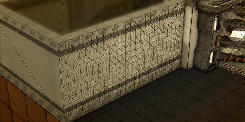
Figure 6. Mesh wireframe after tessellation. No damage has been applied.
When an untouched face is damaged for the first time a few things happen. First the display mesh, which up until this point was a two triangle plane, is tessellated. Similar to how the resolution of the damage buffer is calculated, there is a mesh density factor which describes "faces-per-meter". I use a value of 6, so my 4 x 2m wall results in a mesh that measures 24 x 12 square sections (576 triangles). The blue channel of the vertex color is used as a boolean value to mark which vertices are on the outermost edges of the plane mesh. This allows me to extrude those vertices in the geometry shader to create the wall thickness you see along the top edge.
Once damage has been applied, the face is flagged and starts to draw using a special damage shader. This shader samples from the damage buffer and uses a geometry stage to cull any faces that are fully damaged and construct a solid tapered edge at the borderline of the damaged area.
Figure 7. Visual representation of the two UV sets (lower) with the textures they sample (upper)
The wall geometry needs to have tiling UVs so the square wall display texture can repeat on long sections without stretching. However, the damage buffer requires unique UVs that map 1-to-1 with the wall geometry so a second set of UVs are generated and stored in the red and green channels of the vertex color. This way each vertex of the wall is mapped to a unique space on the damage buffer.
This next bit is the part where I try to describe a shader using words.
If you prefer to just read the pseudocode, scroll down a bit further.
In the geometry shader each triangle of the mesh is processed independently. The UVs from the three vertices of each triangle are sampled from the damage buffer to determine if any of them should be fully discarded. If all three vertices are damaged beyond the threshold value then the entire triangle is discarded and the shader returns.
If none of the triangle vertices have any damage then the triangle should just be drawn normally. These triangles actually need to be drawn twice: once regularly and then again extruded inwards with the normal and winding order inverted. This makes the wall look double-sided and gives it its thickness. Before finishing, the shader will also check if any of these vertices are edge vertices via the vertex color attribute we used earlier. If it is an edge vertex the shader will generate flat geometry to cover the top edge which masks the hollow area between the two wall faces.
The last case is the most involved. In this case one or more of the three vertices has a damage value greater than 0 but below the threshold of "fully damaged". The position of the damaged vertex is transformed so the more damage a vertex has the more it will be pushed inward, both into the wall and toward it's neighbour vertices. This transform is applied to the original vertices as well as the inverted "inner wall" vertices. The resulting effect is a polygonal edge that shrinks and grows closer together as more damage is applied, making the wall geometry thinner and thinner until the damage value has reached the threshold and the geometry is fully discarded.
If a triangle is partially damaged like this then that also means it's on the leading edge of a damaged area, so a bridge of geometry is generated between the two sides of the wall. This serves a similar purpose to the top edge geometry in that it masks the hollow area inside the wall exposed by the damage.
Damaged vertices interpolate between the regular wall texture and a noisy damage effect texture depending on how damaged they are, to give the edge a messy mangled appearance. The normals for all the damaged, modified geometry are also recalculated when the vertices are transformed.
// If two vertices from this triangle lie
// on the edge of the mesh then we want
// to generate an extruded edge to cover the gap
if (edgeCount > 1)
{
renderEdgeTrim();
}
return;
}
//
// At this point we know the triangle must be partially damaged
//
// This function moves the vertices into their new
// positions based on damageValue[] and re-calculates
// normals from these new positions.
transformDamagedVertices();
// Figure out where we need to generate a skirt to
// cover up partially damaged edges
// Generate two skirt edges adjacent to the
// culled vertex renderSkirtEdge takes the
// indices of the two input vertices for which we
// want to draw the skirt
// Render using tranformed vertex positions
// from transformVertices()
renderTransformedTriangle(false);
// Render the same triangle flipped
renderTransformedTriangle(true);
}
This all demonstrates why the display mesh needed to be tessellated. The damage shader works on a per-vertex basis so the higher the density of the mesh, the more detailed the damage will appear.
Relative to other shaders used in the game the damage shader is less performant, so the fewer vertices it needs to process the better. The tesselation density ("faces-per-meter") used in the game was chosen because increasing the density did not result in a noticeable visual improvement. Just one of the advantages of making a game where the camera is pulled way back.
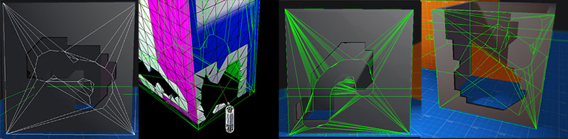
Figure 8. Damaged wall as it appears in game, wireframe overlay, and normals
5. Collision
Return to index
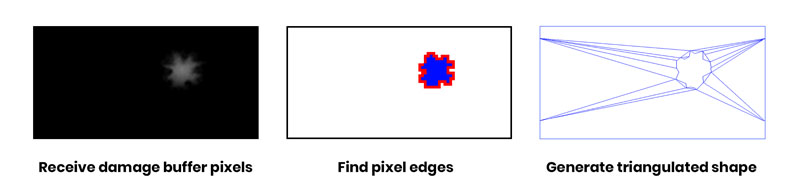
Any time a face receives damage the collision shape needs to be updated to match. This is done by extracting an outline of the affected area from the damage buffer and triangulating that outline into a new collision shape.
Figure 9. Drawing to and erasing the damage buffer using editor tools. The collision shape is visible in white.
To analyze the pixel data a copy of the damage buffer needs to be transferred from video memory to CPU-side memory. This can end up being a very slow operation which causes a stall in the render pipeline. To avoid this performance hit it's possible to trigger a request for a copy of the damage buffer as soon as the damage is applied, but the damage buffer data is not actually received until the next frame. This allows the graphics driver to defer the transfer operation until a time when it will have a lessened impact on performance. This means that the collision shape will have a one frame delay before it matches the shape of the damaged face, but this isn't noticeable even when running the game at low framerates. Without this technique there would be very distracting frame drops anytime a wall is damaged.
Retrieving damage buffer from VRAM without a stall
// Damage event is triggered, damage sprite is drawn to damage buffer.
// ...
// Read pixels from damageBuffer into pixelBufferObject.
// Binding a PBO and calling glReadPixels with a null destination allows
// the driver to transfer the data into the PBO asynchronously,
// preventing a stall.
// Render, Swap
// ...
// -- New frame begins ----------------------
// Destructible wall entity is waiting for pixel data from the last
// frame. When the wall entity gets updated it maps the pixel buffer
// object and retrieves the pixel data.
The damage buffer pixels now need to be analyzed to extract an outline of the damaged area. A marching squares algorithm is used to scan through the pixels and find the edges of any bright shapes indicating a damaged area. This involves a few magic threshold and epsilon values which have been tuned through trial and error to provide a reliable result. This returns a set of 2D shapes whose edges are derived from pixel coordinates. These shapes are then simplified to remove extraneous noise and detail.
Figure 10. Generating a new collision shape from a bitmap
All the required information has been gathered, now the new collision shape can be built. The simplified shapes are fed into a triangulation library which returns a set of triangles that match the contours of the input shapes. The original intact collision shape is discarded and a new more complex collision shape is built. This is made easier by the physics library which has a specific collision shape type that can be generated from a list of triangles.
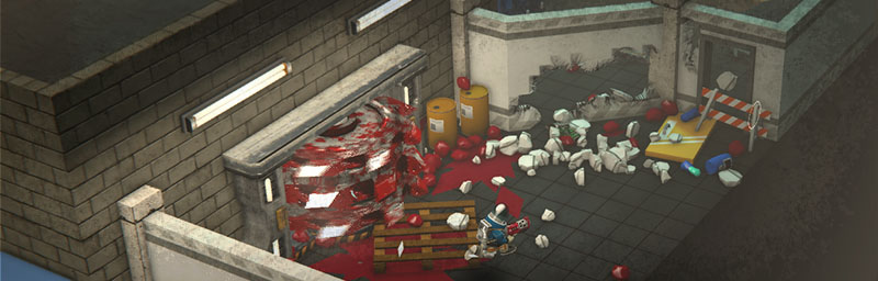
Since they each reference the same source damage buffer, the gaps in the triangulated collision shape will match the gaps in the display mesh. Now you can walk through a wall!
6. Navigation
Return to index
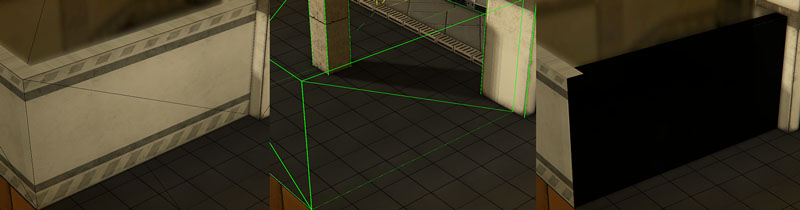
Navigation for NPCs in Radio Viscera uses a node-based A* solver. Path node entities are placed throughout a level and then automatically linked together using visibility and accessibility checks from node to node. If an NPC needs to travel to a new location, it will run a path solver between the node nearest the destination and the node nearest to the NPCs current location.
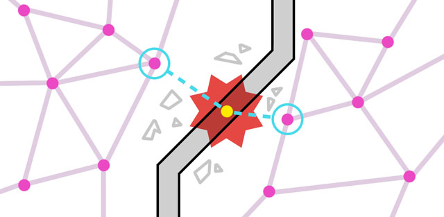
Figure 11. Magenta lines are the navigation graph, the red line is the direct route to the NPCs destination and the green line is the planned route.
To navigate through a destroyed wall NPCs need to know if they can pass through at that location. The navigation network needs to be updated in response to damage events.
Figure 12. Top down view of the navigation graph after a damage event
When a damage event happens a search is done on the path node network to gather all nodes within a certain radius of the hit. From this set the two closest nodes on either side of the damageable face are selected and a visibility check is performed between them. If the two nodes have a clear line of sight to each other then that means the damaged area is large enough for a character to pass through. Connecting these two nodes directly sometimes results in oblique paths which are more likely to cause characters to get stuck. Instead, a new temporary path node is inserted into the graph on the ground directly beneath the damaged area to create a more orthogonal route. The two original nodes are bridged by the new temporary node and now NPCs can safely path find through the wall as if it had never been there. These nodes are labeled "temporary" because they're never saved and wiped anytime the level resets.
Figure 13. Crouching played at half speed to demonstrate the effect
Due to the size and shape of character collision bodies often a character will get stuck trying to fit through a hole that *looks* like it should be big enough to fit through. To remedy this issue characters will continually perform a series of raycasts to detect if their heads are colliding with a wall, and also check that their mid-sections are *not* colliding with a wall. If this is the case then the character knows they're only banging their head against the top edge of a wall hole and should crouch down to fit through. When these conditions are met the character's collision body is scaled down on the Y-axis so it can squeeze through the gap. Once the character has passed through the wall the raycasts will no longer detect anything and the collision body returns to its normal shape. During this process the character model is also scaled down in sync with the collision body to fake the appearance that they are briefly ducking to fit through the gap.
Figure 14. The Bully NPC doesn't even know there's a wall there
One special case in regard to character navigation is this big charging NPC (nicknamed "Bully") who can smash through walls with their body and knock the player character into the air. Originally I tried to make this work as the system normally would, where the NPC would smash into the wall, creating a hole, and then navigate through the newly created opening. It was difficult to make this approach work and still have the NPC smash the wall at full speed without stalling, changing direction or getting stuck. The solution was to disable collision between that specific type of NPC and damageable walls, while still detecting the collision events and applying damage to the wall. This gives the illusion that the wall was smashed by the NPC and the NPC is able to maintain its speed throughout the attack. Additionally, the navigation logic for this NPC was tweaked to ignore damageable walls when performing visibility checks. This allows the NPC to navigate to its destination in a straight line without worrying about the "correct" path to take.
To enhance the impact of the wall damage there are a handful of secondary visual and audio effects which are triggered.
Figure 16. Impact effect
The first of these is an impact particle effect. It's responsible for the sudden flash and ejects very bright fragments away from the hit position along the damage normal. They're given a high starting velocity with a large drag coefficient so they burst out quickly and then immediately start to slow down. The mesh for each particle is a generic chunky piece of geometry, the same mesh used for the debris pieces that fall to the ground. The color of each particle starts at RGB [1600, 1600, 1600] and uses an exponential easing function to fade down to [255, 255, 255] as its transform scales to zero. The lifetime of each particle ranges from 0.5-4.0 seconds.
Figure 17. Dust effect
The second particle effect is used to simulate dust and debris hanging in the air after the wall has been hit. The particles from this effect use camera aligned billboards with an alpha blended debris texture. Each particle has its own random angular velocity to give a roiling effect.
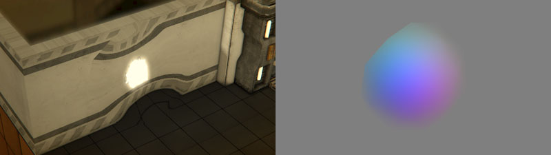
Figure 18. Scene view with corresponding displacement buffer
Screenspace displacement is used to briefly distort the area around the hit and enhance the feeling that these are big, destructive, energetic impacts. While rendering the scene, a low-poly sphere is drawn to a separate framebuffer (figure 18) specifically for displacement entities. Once the main scene render is finished the post-filter stack is applied, this includes things like ambient occlusion and depth of field. There's a special screenspace displacement post-filter at the top of the stack that samples the displacement framebuffer to distort the pixels of the final scene. The sphere begins at full scale then quickly shrinks in an attempt to imitate the effects of negative pressure seen after a large blast wave. The scaling is applied over a period of 0.5 seconds and uses an exponential easing function to keep it quick and snappy.
To help make the interaction feel more physically grounded a group of wall debris pieces are spawned at the impact position and then are each given a strong physical impulse in the direction of the damage normal. These chunks are sourced and recycled from a pool of debris entities which is also used for glass shards and gore pieces. To be physically correct these chunks should probably be flying *inward* from the hit, but that's way less fun to see.
The sound effect used for the impact is a mashup of a few tumbling sand and rock samples with a bassy kick drum. This provides a nice low "thump" which then transitions to higher frequencies for dust and debris effects.
Rubble sound effect
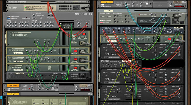
It's worth mentioning the player's weapon sound since it's almost always heard in concert with the rest of the damage effects and does a lot of heavy lifting in giving the hit a good "punch" sound. I wanted to make use of parametric audio tools when creating the sound effects for anything inorganic on this project, so this effect was built in Reason. Like the rubble effect it consists of a kick drum sample run through a heavy distortion effect mixed with four synthesizer patches which each provide a unique component to the final layered result.
Weapon sound effect
Figure 19. Creative wiring in Reason forcing all the instruments to trigger at once
8. Doors
Return to index
Sometimes an NPC will need to move between two sections of a level separated by a wall that hasn't been damaged yet, so a door is needed. Adding doors to damageable walls took a few attempts to get working correctly. The damage system is designed around noisy, chaotic blasts whereas a doorway needs to be a very exact shape and positioned precisely.
Figure 20. Early door problems
On my first attempt I tried to make use of the damage system and draw white rectangles to the damage buffer, effectively punching perfect rectangular holes which would then have door frames placed in them. One of the drawbacks to this method was that if a wall had a doorway punched out of it then it would be required to always be in a damaged state even if the player hadn't touched it, nullifying the performance advantages of drawing a clean, un-damaged wall. Sampling from the low resolution damage buffer was also imperfect so doorways would often end up having irregular shapes.
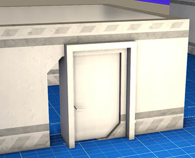
Figure 21. Adding a door in the editor
Part way through production I switched from defining the footprint of damageable walls as rectangular boxes to using a fencepost-style system to define the 2D bounds of a room in 3D space (Figure 21, visible in green). One of the features of this change was the ability to disable sections of a wall so that it would not generate a damageable face along that edge. I added tools which allow me to "stamp" a door into a wall, splitting the selected wall and inserting an extra section that has its wall generation disabled, effectively creating an empty gap. The doorway is placed in this newly added gap and a fake header mesh is added above the frame. The header mesh is specially created to fit in that little gap and has no collision, which makes it far easier to fling NPCs through doors.
Figure 22. Get that junk out of here
The door panels themselves are dynamic collision bodies with a hinge constraint which allows them to swing freely within a certain range. The hinge constraint also provides a motor API which is used to return the door to its closed position. When a door panel has received enough damage the hinge constraint is disabled and the door is smashed out of the frame.
9. Notes
Return to index
This system was not meticulously planned from the start. It grew from experiments with culling faces with compute shaders and evolved as the game was refined into the final product.
Figure 23. One of the earliest tests
Unlike some modern dynamic destruction systems which offer more unified destruction with different material properties and preservation of mass, this system has been developed very specifically to offer walls that are fun to shoot at. Since I was focusing on that one goal I was able to apply my time trying to make it feel fun rather than focusing on creating a global damage system that can work under many different circumstances. This is one of the reasons why I've focused this article on the concepts behind the system, any technical specifications I presented would only be applicable if you intended to make this exact game over again.
Figure 24. Matching collision shapes to the damage buffer was tricky
In terms of performance this system isn't particularly memory hungry, the damage buffers are fairly low res, but there are some bottlenecks. Scanning through the damage buffer to detect outlines is the slowest part on most machines, which is a big reason why the damage buffers are low resolution. Using higher resolution damage buffers would not add much visible detail and the cost of walking through the bitmap would increase substantially.
The geometry shader itself is also quite processing intensive on a frame-to-frame basis due to all the math for re-constructing the positions and normals for the damaged edges. A much more efficient method would be to use compute shaders to scan the damage buffer and rebuild the mesh only when the damage buffer is touched. However this project was developed to run on an OpenGL 3.3 context where compute shaders are not supported.
 This is an overview of the dynamic damage system created for the videogame Radio Viscera.
I've written this article with a focus on the concepts used rather than a specific language or environment or as a step-by-step guide. The implementation described here was built very specifically for the game I was making, so including the technical minutiae here did not seem helpful. Hopefully some of this information will help you in the development of your own project using whichever engine or environment suits you best.
I've tried to insert as many gifs, screenshots and sounds as I could to keep it from being too dry. The last few sections focus on the (less technical) secondary systems and effects that interact with the destruction and should be a bit more digestible.
This design was built in a custom C++ based game engine which uses an OpenGL renderer and the Bullet Physics SDK.
1. Overview
2. Initial face generation
3. Detecting raycasts and applying damage
4. Drawing a damaged wall
5. Collision
6. Navigation
7. Effects
8. Doors
9. Notes
This is an overview of the dynamic damage system created for the videogame Radio Viscera.
I've written this article with a focus on the concepts used rather than a specific language or environment or as a step-by-step guide. The implementation described here was built very specifically for the game I was making, so including the technical minutiae here did not seem helpful. Hopefully some of this information will help you in the development of your own project using whichever engine or environment suits you best.
I've tried to insert as many gifs, screenshots and sounds as I could to keep it from being too dry. The last few sections focus on the (less technical) secondary systems and effects that interact with the destruction and should be a bit more digestible.
This design was built in a custom C++ based game engine which uses an OpenGL renderer and the Bullet Physics SDK.
1. Overview
2. Initial face generation
3. Detecting raycasts and applying damage
4. Drawing a damaged wall
5. Collision
6. Navigation
7. Effects
8. Doors
9. Notes